


To Infinity and Beyond: Ultra-Large-Scale Systems Complexity
Off-the-scale complexity requires special architectural methods.

Pop quiz: Define Ultra-Large-Scale (ULS) systems and give two examples.
Answer: ULS systems are those of such size, scope, and most importantly, complexity, that ordinary system architectural and design methods are ineffective and indeed, even just understanding the system behavior is overwhelmingly difficult. ULS systems are characterized by the following:
Decentralized data, control, and development
Inherently conflicting diverse requirements
Continuous (or at least long time scale) evolution and deployment
Heterogeneous, inconsistent, and changing elements
Wide time scales
Wide geographic scales
“Normal” failures (failures are common, not rare exceptions)
Example 1: The U.S. healthcare system (this was pointed out to me by Linda Northrup of Carnegie-Mellon University, where she and her colleagues laid down many of the principles of ULS system theory).
Example 2: Regional and continental scale electric power systems, such as the U.S. Eastern Interconnection (which has been described as the largest machine ever built).
The reason for the ULS complexity of power systems is rooted in structure, or rather structures and scale: electric power systems are made up of many large structures, each of which is highly complex in itself. These structures are interconnected in highly complex ways. and this (complex structures interconnected in complex ways) leads to an exponential complexity effect. ULS complexity has been a significant obstacle to modernizing what we often call “the grid” since ordinary methods of dealing with ULS complexity systems are inadequate. As an example of the consequences of ULS complexity, I have seen several times how incremental changes to the grid created unforeseen and unfortunate consequences because there was no way to understand the entire system and trace (in advance) the effects of a change in one part of the grid to all the other parts. The method I developed for doing this tracing for ULS systems was later adopted by others as a means to assess electric grid cyber security vulnerabilities.
To address this dilemma, first recognize what a system architecture is and what is is used for.
A system architecture is the highest level description of a system, and it enables reasoning about the system’s properties and behavior. It is is a key tool to help understand and define the many complex interactions that exist in complex systems. A system architecture consists of three parts:
structure
black box component
externally visible characteristics
The structure aspects of the architecture specify the overall “shape” of the system and determine the limits on what the system can do and, equally importantly, what it cannot or must not do. The components are called “black box” because at this level we are not concerned with how the components work or are implemented, only what they do. Component internal designs are the domain of the component developers. Externally visible characteristics have to do with how the build/operators and the users of the system see its behavior.
A system architecture provides an enforceable set of constraints that comprise the least number of limitations necessary to ensure the resulting system will operate as required. Among other things, a system architecture specifies how components are interconnected, identifies and defines interfaces and platforms, and selects the characteristics that determine system behavior.
Note that an architecture is not quite the same as an architectural specification package, which is the work product that documents an architecture.
A system architecture is not a design and in fact admits many possible designs as long as the architectural constraints are observed. A system architecture is the key input to system and solution design processes and serves to identify legacy constraints and gaps in technology and organization, to remove barriers and define essential limits to new functionality, and to assist communication among stakeholders. As such, we want to prepare this first, before any design processes begin. Well-planned system structure simplifies downstream decisions and frees up developers and engineers working on individual components or systems to employ creativity with assurance that unintended consequences will not crop up to hamper or even invalidate their work. A bonus of the ULS architecture approach is the clarity it provides around complex issues and the consequent risk management it brings to problems like electric grid transformation.
So, pretty handy, right?
There are many methodologies for creating ordinary system architectures - consider TOGAF for enterprise software systems, for example. These methods are driven by (I would say “hung up on”) use cases and design patterns (small chunks of block diagrams) that do not extend well to ULS systems. So, let’s look at a basic view of how to create ULS system architectures.
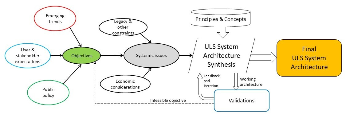
Figure 1 below shows a conceptual flow from architectural elements to system objectives. It goes through a box called systemic issues that is described below.

This diagram gives a few hints on how to proceed but what we want is a flow that starts at objectives and ends with the the architecture we need. Figure 2 shows a high level version of the process I have used to develop ULS architectures.
This makes more sense as a synthesis process; it proceeds from requirements through several key artifacts to the final architecture specification, in common with almost all such processes. One difference that comes from ULS theory (there are many others) is that the requirements definition process focuses on producing a set of systemic issues (cross-cutting problems affecting much or all of the system) rather than use cases and these issues drive the architecture synthesis. The problem with use cases as regards ULS systems is that there are far too many of them (catalogs of use cases for the so-called “Smart Grid” run into the thousands of entries - a symptom of scale). Such use case sets are not comprehensible or even navigable and so do not lend themselves to determining a cohesive architecture, plus there is a second problem: it is never possible to know when the set is complete. Systemic issues groups are much more compact than use case sets and lend themselves well to identifying structural issues and solutions in ways that use cases cannot.*
Another difference is the use of a set of architectural principles in the synthesis phase. We have defined a number of principles that account for ULS system properties and provide ways to think through complex structure issues while avoiding a variety of errors that are not obvious until implemented at scale. Architecture development is more than just a matter of tabulating use cases and then drawing a block diagram or a cloud illustration. In the ULS architecture discipline, we have compiled structural guidelines that are induced by math drawn from optimization theory, graph theory, network theory, resilience theory, and other disciplines. These guidelines are easy to apply and do not require the architect to solve equations. We did the math so you don’t have to!
To understand the Architecture Synthesis box in Figure 2 a bit more, let’s look at a sort of philosophical side issue: cohesive architecture. In plain terms, a cohesive architecture is one that “hangs together” when considered as a whole. Figure 3 shows one way to visualize this.
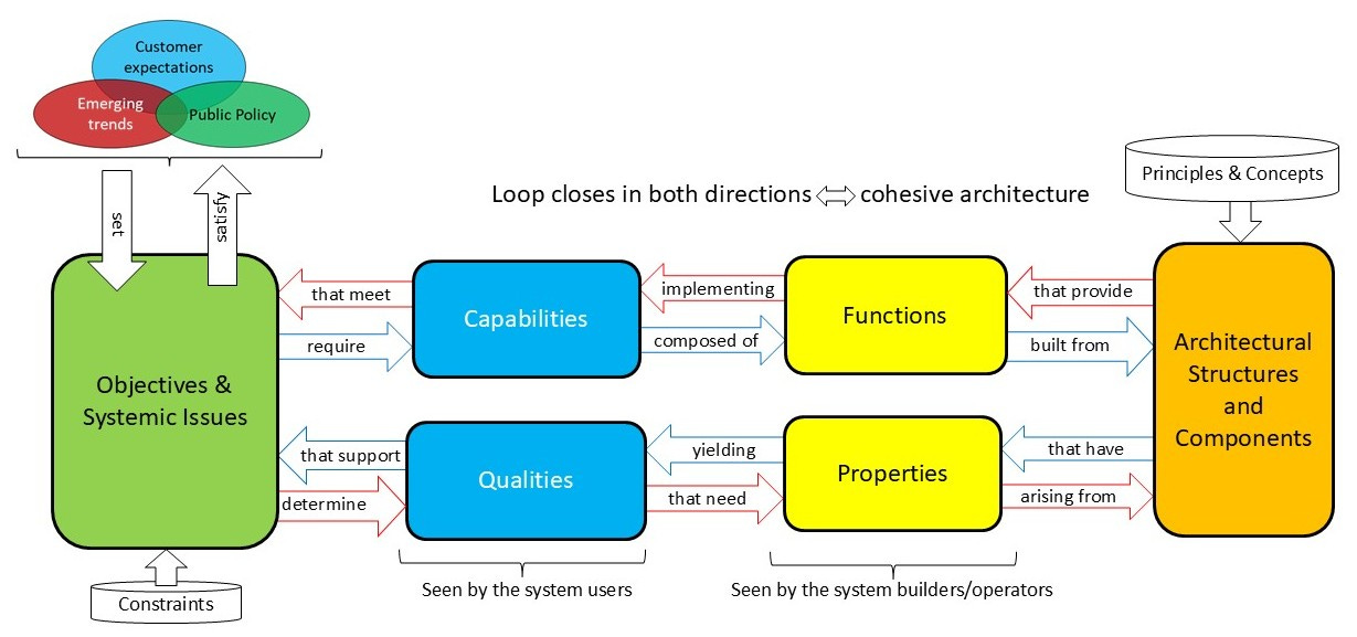
The diagram has two loops, the inner loop (blue arrows) goes from objectives to capabilities and functions; the red outer loop goes from objectives to qualities and properties. For a “good” architecture, the two loops should close (meaning that the architecture does in fact support the objectives when viewed in different ways). When both loops close for a single architecture, we can say the architecture has a good degree of cohesion.
Now, trying to specify an architecture that closes both loops simultaneously over the complete set of elements shown in the diagram is massively difficult. So another approach might be to choose only one of the loops to work on. Figure 4 shows this using just the inner loop.
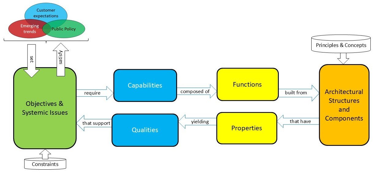
This version of the process starts as many people would, by determining a set of capabilities needed by the objectives and then moving on to define functions. An architecture is synthesized from the functions, but only then can the system properties and qualities be determined (as emerging from the architecture), with the hope that the loop closes. If not, the architecture and possibly the functions and capabilities must be adjusted iteratively to try to get the loop to close. Not too easy - don’t do that.
What if we use the outer loop instead? Figure 5 shows this approach.
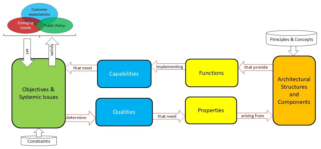
This also starts in what looks like a reasonable way. Objectives are translated into required qualities, and then properties, which lead to an architecture. But now, we must figure out the inferred set of functions that could be implemented, and the capabilities they could support, in the hope that this loop closes. Unfortunately, this involves bottom-up thinking, from architecture to functions to capabilities. Worse, it is very difficult to specify architectural components without knowledge of the necessary functions, so when this loop does not close, a significant amount of iteration is needed, and not just in the structures and components. This way is worse - don’t do that either.
Do this:
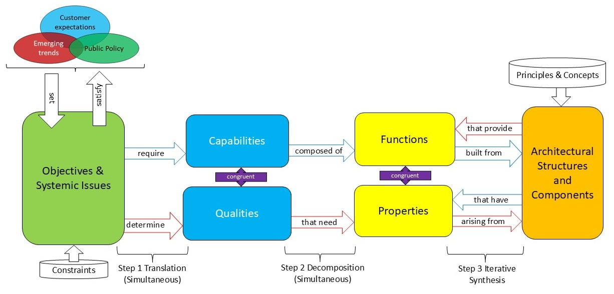
Figure 6 shows a three step process:
Translate objectives into capabilities and congruent qualities simultaneously.
Decompose capabilities into functions and do the same with qualities simultaneously to get properties congruent to the functions.
Synthesize the architecture structure and components by iterating against just the set of functions and properties; when the short loops are closed, closure of the full loops is guaranteed because of the first two steps.
There is still the issue of how to actually choose the structures and components. This is where the principles and concepts come in, but this also requires creativity and a goodly amount of experience. Some amount of iteration is still necessary, but doing so with the short loops is much easier than trying to do it across the long loops.
There is a lot more to all this in practice - I wrote a 242 page guidebook at PNNL just to explain the basics of how to apply ULS architecture to electric power grids. You can read more about the principles and advanced concepts as applied to electric power systems on the PNNL Grid Architecture website: PNNL Grid Architecture
*The misuse of use cases is a topic for another day.