
General Three-Phase Waveform Preprocessor
A front end for three-phase digital instrument, protection, and control applications.

Digital signal processing for three-phase electric power systems is often done in a rather unsophisticated fashion. Synchrophasors are calculated using blocks of data one or two power cycles long so that FFTs can be performed (this is because one of the key methods employed in this approach must operate in the frequency domain), leading to significant latency and averaging effects. Many methods rely upon the unjustified assumptions of balanced phases and steady state conditions and so do not handle realistic phenomena well.
Employing certain more powerful methods, we can develop a digital preprocessor for transforming sampled three-phase voltage waveforms into phasors and symmetrical components. It operates in the time domain with very low latency, high time resolution, no restriction on phase unbalance, and which can measure and adapt to system frequency changes on a low latency basis. To do this, we need to consider five mathematical tools:
Clarke transform - matrix transformation that converts three-phase digital waveforms to a quadrature signal and a real signal. This is widely used in control of three phase AC motors but the complication here is understanding how unbalanced three-phase waveforms are represented in the output of the Clarke transform. That understanding is key to extraction of symmetrical components.
Differential conjugate operator - this is a simple method to use the present output of the Clarke transform and one past time sample to obtain the system digital frequency (which yields system angular frequency via division by the sample period).
Complex filter - digital filter with complex coefficients, important here because it can be used to separate positive and negative frequencies, that being crucial for handling unbalanced three-phase systems.
Complex demodulation - standard communication theory method for frequency downshifting a complex signal. Makes use of a quadrature oscillator and a complex multiplier.
Fortescue transform - matrix transformation that can reconstruct phasors from a set of symmetrical components.
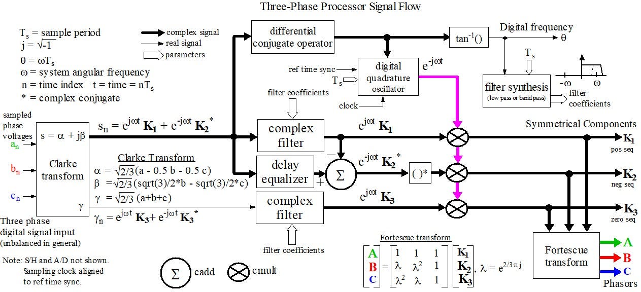
The figure below shows the signal flow for the preprocessor.
The inputs, a, b, and c are the digitized voltage waveform sample streams for the three phases of the power system (subscript n is a time index and t = nTs is time at index value n). The K values are the positive sequence, negative sequence, and zero sequence primary phasors. The outputs A, B, and C are the phasors for the three phase signals a, b, and c.
Concept of Operation
The previously digitized three-phase voltage waveform streams are converted by the Clarke transform into a complex signal s and a real signal γ. Signal s can be expressed in terms of the positive and negative sequence sequence symmetrical components and the real signal γ can be expressed in terms of zero the sequence symmetrical component [1]. Both signals involve positive and negative frequencies. Complex filters are used to separate positive and negative frequencies in both outputs of the Clarke Transform. The filters must be complex (i.e. have complex coefficients) to do this [2],[3].
The modulated positive sequence is subtracted from the signal s to isolate the negative sequence. Once the modulated positive and negative sequences are isolated, complex demodulation is used to obtain the K values. The signal γ is filtered using another instance of the same complex digital filter to isolate the zero sequence, which is then demodulated. The complex digital filter can be either a low pass filter or a bandpass filter and in fact it could be a high-Q notch filter that removes the negative frequency component (but that requires very close system frequency tracking). The coefficients could be static but if the filter synthesis is online, then the filter coefficients can be continually updated to track system frequency.
If the phasors will only be used locally, then the reference time sync signal can be generated locally. If phasors from various remote locations will be combined, then a time sync signal must come from a source common to each location, such as global navigation satellite systems (GPS/GLONASS) or communication network time sync such as Precision Time Protocol service (IEEE 1588).
System frequency is easily extracted from the s output of the Clarke transform using a neat trick from Spagnolini [4], which I subsequently adapted and named the differential conjugate operator. The operator for complex signal s is sns*n-1 where * denotes complex conjugate. The complex output then drives the quadrature oscillator needed for complex demodulation. The digital frequency can be obtained using an inverse tangent and this can be used by applications but also as an input to the filter synthesis algorithm, which is how the filter and demodulators can track system frequency. For applications that can tolerate slightly less accuracy, a small angle approximation can be used to eliminate the inverse tangent calculation.
Finally, once the symmetrical components are extracted, the phasors corresponding the the three voltage waveforms can be reconstructed using the Fortescue transform. Note that all of the outputs are updated on every waveform sample period (not on power cycles). The maximum output delay depends on the order of the complex filter, so for a recursive filter implemented as a single biquad section, the output delay would be 2 Ts as opposed to the 256 to 512 Ts delay of the one and two power cycle FFT-based methods.
The preprocessor provides phasors, synchrophasor symmetrical components, and system frequency as outputs. The Clarke transform output signals can also be used for protection and control applications (AC motors, inverters). A wide variety of applications can be built using this preprocessor as a general front end for three-phase signals.
And look, ma - no FFTs!
References
Neves et al, “A Generalized Delayed Signal Cancellation Method for Detecting Fundamental Frequency Positive Sequence Three-Phase Signals,” IEEE Trans. on Power Delivery,July 2010, Vol. 25, No. 3, pp. 1816-1825.
Zlatka Nikolova, Georgi Stoyanov, Georgi Iliev and Vladimir Poulkov, “Complex Coefficient IIR Digital Filters,” Digital Filters, Chap 9, edited by Prof. Fausto Pedro Garcia Marquez, Barnes & Noble, 2021.
Andrew J. Noga, “Complex Band-Pass Filters for Analytic Signal Generation and Their Application,” Air Force Research Laboratory, AFRL-IF-RS-TM-2002-1, July 2001.
Umberto Spagnolini, “2-D Phase Unwrapping and Instantaneous Frequency Estimation,” IEEE Transactions on Geoscience and Remote Sensing, Vol. 33, No.3, May 1995.